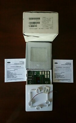
Download Installation instructions manual of Carrier EDGE Pro Thermostat for Free or View it Online on All-Guides.com.
Brand: Carrier
Category: Thermostat
Type: Installation instructions manual for Carrier EDGE Pro
These instructions cover the physical installation and start up of the ComfortChoice system. Install thermostat in non-condensing areas with ambients between 30°F and 104°F (0°C to 40°C). Install the Utility I/ O board in non-condensing areas with ambients between-4°F and 158°F (-20°C to 70°C). The auxiliary load. The Edge Pro thermostat by Carrier is a wall-mounted, low-voltage control which combines temperature and humidity control in either a single or two-piece unit. The Edge Pro ther-mostat can be set for 7-day, 5/2-day, or 1-day programmable operation. Different heating and cooling set points and times are programmable for 2 or 4 periods per day. Carrier Parts A-F. Carrier AC Parts; Carrier Blower Motors. Installation Manuals: 035-000051-001 Installation Manual - 035-000051-001 Installation Manual.pdf.
Pages: 28
Manufacturer reserves the right to discontinue, or change at any time, specifications or designs without notice and without incurring obligations.
Catalog No. 04-53330026-01Printed in U.S.A.Form 33CS-74SIPg 1 6-13Replaces: 33CS-66SI
Part Numbers 33CS2PPRH-03 and 33CS2PP2S-03
SAFETY CONSIDERATIONS. . . . . . . . . . . . . . . . . . . . . . 1
GENERAL. . . . . . . . . . . . . . . . . . . . . . . . . . . . . . . . . . . . . . . .1
PACKAGE CONTENTS . . . . . . . . . . . . . . . . . . . . . . . . . . . 1
INSTALLATION CONSIDERATIONS. . . . . . . . . . . . . .1,2
Control Configuration. . . . . . . . . . . . . . . . . . . . . . . . . . . .1
Outdoor Temperature Sensor . . . . . . . . . . . . . . . . . . . . 2
Remote Indoor Temperature Sensor. . . . . . . . . . . . 2
INSTALLATION. . . . . . . . . . . . . . . . . . . . . . . . . . . . . . . . . 2-6
Thermostat Location. . . . . . . . . . . . . . . . . . . . . . . . . . . . . 2
Carrier Edge Thermostat Installation
Wiring Requirements. . . . . . . . . . . . . . . . . . . . . . . . . . . . . 2
Two-Piece Installation. . . . . . . . . . . . . . . . . . . . . . . . . . . . 2
Single-Piece Installation . . . . . . . . . . . . . . . . . . . . . . . . . 5
Power . . . . . . . . . . . . . . . . . . . . . . . . . . . . . . . . . . . . . . . . . . . . 6
(33CS2PPRH-03 Model Only). . . . . . . . . . . . . . . . . . . . 6
CONFIGURATION . . . . . . . . . . . . . . . . . . . . . . . . . . . . . .6-11
To Enter and Exit Configuration Mode. . . . . . . . . . . . 6
Configuration Mode. . . . . . . . . . . . . . . . . . . . . . . . . . . . . . 6
Configuration Options . . . . . . . . . . . . . . . . . . . . . . . . . . . 7
SYSTEM START-UP AND CHECKOUT . . . . . . . . .11,12
Installer Test Mode. . . . . . . . . . . . . . . . . . . . . . . . . . . . . . 11
Default Schedule. . . . . . . . . . . . . . . . . . . . . . . . . . . . . . . . 11
and Holiday Settings. . . . . . . . . . . . . . . . . . . . . . . . . . . 11
(33CS2PPRH-03 Model Only). . . . . . . . . . . . . . . . . . . 11
Holiday. . . . . . . . . . . . . . . . . . . . . . . . . . . . . . . . . . . . . . . . . . 12
OPERATION. . . . . . . . . . . . . . . . . . . . . . . . . . . . . . . . . . .12,13
Unoccupied Overrride. . . . . . . . . . . . . . . . . . . . . . . . . . . 12
Timers . . . . . . . . . . . . . . . . . . . . . . . . . . . . . . . . . . . . . . . . . . 13
Heat/Cool Set Points (Desired Temperature). . . . . 13
Equipment On Indicators. . . . . . . . . . . . . . . . . . . . . . . . 13
Indicators. . . . . . . . . . . . . . . . . . . . . . . . . . . . . . . . . . . . . . 13
®
Auto Changeover . . . . . . . . . . . . . . . . . . . . . . . . . . . . . . . 13
Emergency Heat Mode . . . . . . . . . . . . . . . . . . . . . . . . . . 13

Dry Contact/Economizer Output . . . . . . . . . . . . . . . . 13
TROUBLESHOOTING. . . . . . . . . . . . . . . . . . . . . . . . . .13,14
Error Codes. . . . . . . . . . . . . . . . . . . . . . . . . . . . . . . . . . . . . 14
WIRING DIAGRAMS . . . . . . . . . . . . . . . . . . . . . . . . . . 14-25
Carrier Edge Thermostat Installation Manual 2
SAFETY CONSIDERATIONS
Read and follow manufacturer instructions carefully. Fol-
low all local electrical codes during installation. All wiring
must conform to local and national electrical codes. Improper
Recognize safety information. This is the safety alert sym-
bol . When the safety alert symbol is present on equipment
or in the instruction manual, be alert to the potential for person-
Understand the signal words DANGER, WARNING, and
CAUTION. These words are used with the safety alert symbol.
DANGER identifies the most serious hazards which will result
in severe personal injury or death. WARNING signifies a haz-
ard which could result in personal injury or death. CAUTION
is used to identify unsafe practices which would result in minor
GENERAL
Carrier’s 7-day, 5/2-day, or 1-day programmable commer-
cial thermostat control is a wall-mounted, low-voltage control
which providestemperature control in either a single unit or a
two-piece unit. The 33CS2PPRH-03 thermostat will provide
both temperature and humidity control. In the two-piece con-
figuration, the relays are located near the equipment and a two-
wire connection is used between the display module (DM, the
user interface) and the equipment control module (ECM). Sin-
gle-piece installation requires more wiring and results in a
higher profile. The thermostat needs no batteries to store user-
configured settings in memory. If power is lost, the internal
memory saves settings for unlimited time and the clock contin-
In the programmable configuration, different heating and
cooling set points and times are programmable for 4 periods
per day or 2 periods per day. Programming can be done for
7 days per week, 5 and 2 days per week, or 1 day. The pro-

grammable control can also be user-configured as a non-
PACKAGE CONTENTS
1 — Stand-off for equipment control module

1 — Pigtail
INSTALLATION CONSIDERATIONS
33CS2PP2S-03 thermostat provides temperature control and
the 33CS2PPRH-03 thermostat provides both temperature and

humidity control. Both models can be configured for air condi-
tioner or heat pump installations and may be configured as
Control Configuration — The thermostat can be in-
stalled in one of two configurations. The thermostat may be in-
stalled as a single piece or it may be split into two pieces and
Carrier Edge Thermostat Manual Pdf
IMPORTANT: Read entire instruction before installing
EDGE
Pro
Commercial Thermostat
Related Products for Carrier EDGE Pro
Related Manuals for Carrier EDGE Pro
Carrier EDGE Pro: Frequently viewed Manuals


